Tutorial: Programming a VizBlock
Description
This tutorial goes through the process of programming your VizBlock using Arduino, allowing you to add custom behaviours and code.
Intro
This tutorial teaches you how to program your VizBlocks using Arduino. You will need the following items for this tutorial:
- A VizBlock
- A micro usb cable to connect the VizBlock to your computer
- A computer
Getting Started
First off, we need to install some software and libraries, which we will use to program the VizBlock
Install Arduino and Packages
- Go to this website and download the appropriate Arduino IDE for your operating system.
- Open the downloaded file and follow the installation instructions (more detailed instructions here).
- Open the Arduino software and then open the preferences window (Arduino>Preferences on Mac OR File>Preferences on Windows).
- In the preferences window enter
https://arduino.esp8266.com/stable/package_esp8266com_index.jsoninto the Additional Boards Manager URLs field. If there are already entries in this field then you can separate them with commas.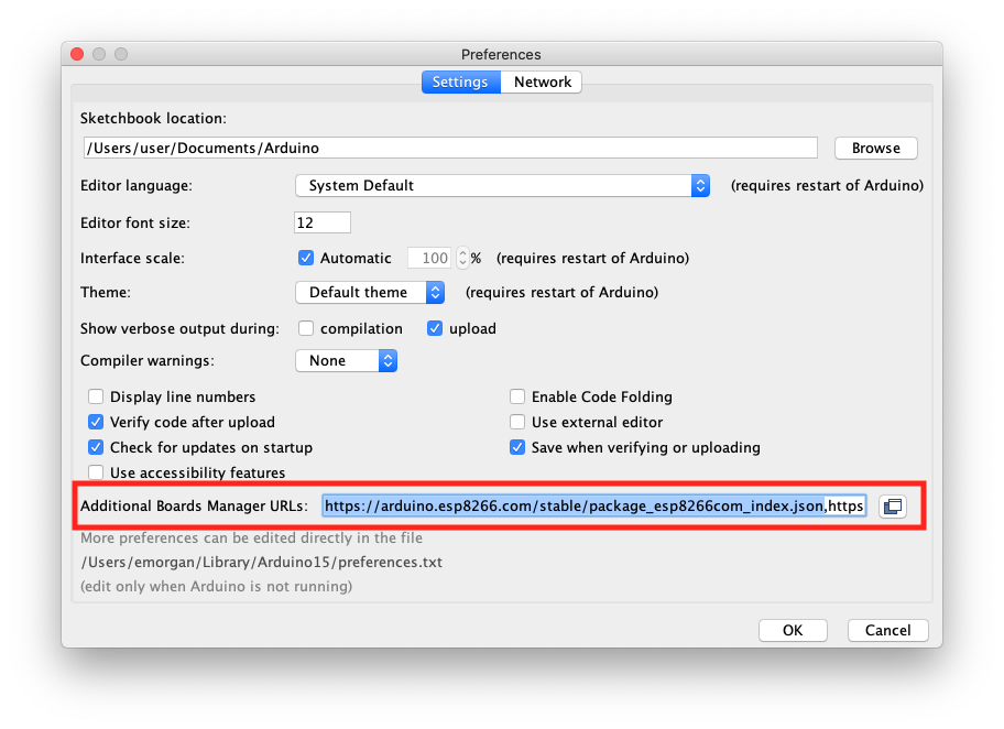
- Open the Board Manager from Tools>Board:>Boards Manager… then enter
esp8266in the search bar, and install the esp8266 package (see image below). Now close the board manager window.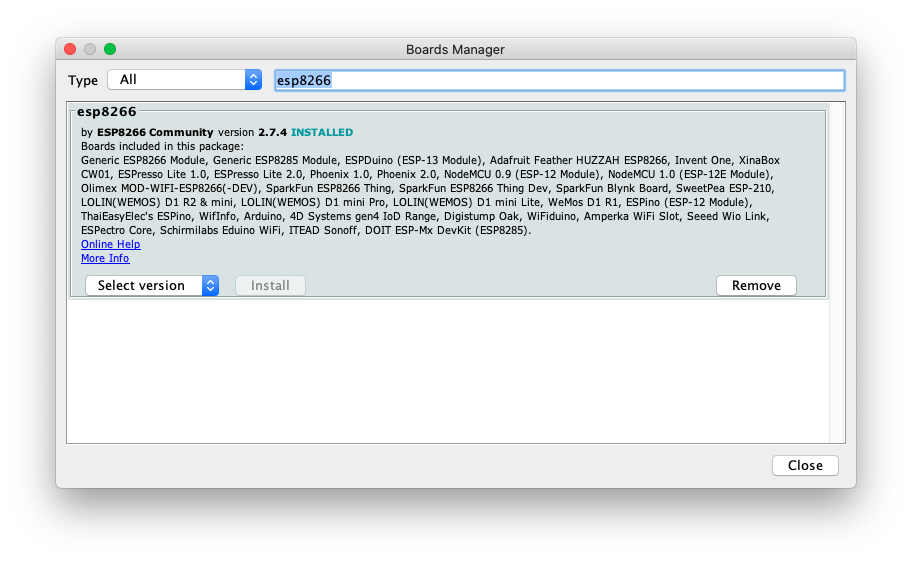
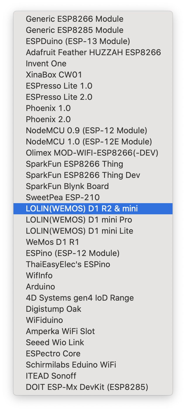
- Arduino needs to know what type of board you want to program, and VizBlocks use the LOLIN(WEMOS) D1 R2 & mini board. Go to Tools>Board:>ESP8266 Boards and select LOLIN(WEMOS) D1 R2 & mini, as shown in the image below.
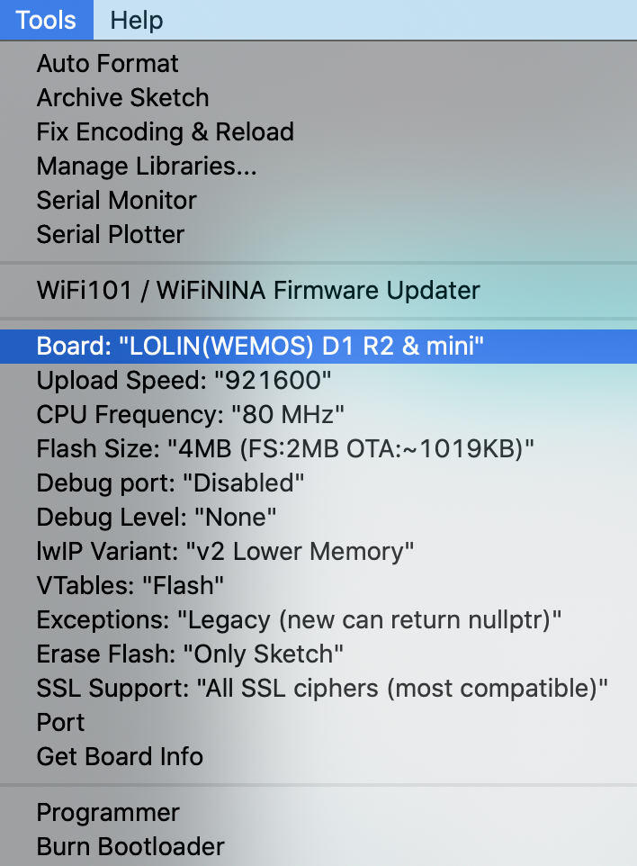
- The tools list will now look something like this:
Install Required Libraries
- In Arduino go to Tools>Manage Libraries
- In the Library Manager, search for adafruit neopixel then click to install the Adafruit Neopixel library.
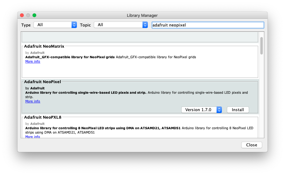
- In the Library Manager, search for adafruit mqtt then click to install the Adafruit MQTT library. If prompted to install missing dependencies, select Install all. Close the Library Manager.
Install the VizBlocks Framework
- Download the VizBlocks Framework Library here.
- In Arduino, go to Sketch>Include Library>Add .ZIP Library…, then navigate to the location of the zip file you just downloaded and open it. In the Sketch>Include Library menu you should now see VizBlocks listed somewhere near the bottom of the menu.
- Quit and re-open the Arduino software.
Check that Everything is Installed
- In Arduino, go to File>Examples>VizBlocks>BasicBlock. This will open an example sketch.
- Click the tick button (verify) in the top left of the Arduino window. It should say Compiling sketch… in the status bar below the code.
- If the status eventually says Done compiling then everything is installed correctly and you’re good to go! If not then you may be missing a required library. Check the error messages for clues, and check that you followed all of the steps above.
Uploading Code to a VizBlock
You should now be ready to upload code to your VizBlocks. This gives you a lot of scope to customise what your blocks are capable of. We’ll start by uploading a basic example sketch that includes the basic configuration and behaviours.
1. Open the BasicBlocks example sketch from File>Examples>VizBlocks>BasicBlock. Let’s take a look at some important parts of this sketch.
2. The following lines are where we configure the basic settings for our block:
VizBlock block(
  "null",         // Our ID (default: null)
  "VizBlocks",    // Wifi Access Point (default: VizBlocks)
  "password",     // WiFi Password (change this to the password for your VizBlocks server)
  "192.168.4.1",  // IP address of Node RED server (default: 192.168.4.1)
  1883            // Port for Node RED server (default: 1883)
  );
3. You will probably need to change the password to the one provided for your VizBlocks server.
4. Further down the page you will see the following lines:
Adafruit_NeoPixel strip(LED_COUNT, LED_PIN, NEO_GRBW + NEO_KHZ800); // Type 1
//Adafruit_NeoPixel strip(LED_COUNT, LED_PIN, NEO_GRB + NEO_KHZ800); // Type 2
These lines are used to set up the LEDs if you are programming an LED block. The // before the second line turns that line into a comment, which means it isn’t read as part of the code - we say it’s “commented out”. The LED blocks use two different types of LED ring and you need to program the block for the right type, otherwise you’ll see your LEDs behaving very strangely. If you’re getting strange LED behaviour then try switching the LED type in the code by deleting the // before whichever line is commented out and inserting // before the line that wasn’t previously commented out. So to switch to using LED type 2, the code would look like this:
//Adafruit_NeoPixel strip(LED_COUNT, LED_PIN, NEO_GRBW + NEO_KHZ800); // Type 1
Adafruit_NeoPixel strip(LED_COUNT, LED_PIN, NEO_GRB + NEO_KHZ800); // Type 2
5. Once you’ve changed the password and selected the LED type (if you’re using an LED block), then you can upload this example code to a VizBlock. First, plug the VizBlock into your computer using a micro USB cable.
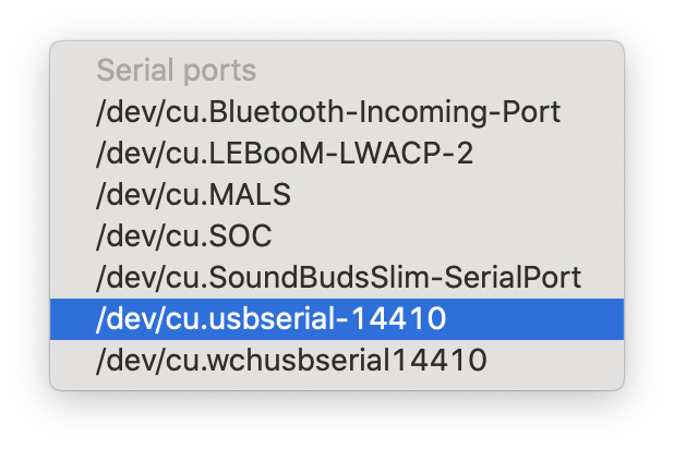
6. Next, go to Tools>Port in Arduino. You will see a list of ports (see Figure below for an example), which will vary according to the devices connected to your computer. You should see a port that includes usbserial (Mac) or COM (Windows). Select this port - or if you have multiple ports then you can work out which one corresponds to your VizBlock by unplugging the USB cable and seeing which port disappears from the list. Note: some USB cables are just built for charging devices and won’t work, so if the VizBlock doesn’t show up in your ports list then try a different cable. You can also try re-starting the Arduino software.
7. Upload the code to your VizBlock by clicking the right-pointing arrow in the top left of the Arduino software. The software will compile the sketch first, then upload it to the VizBlock. You will see a progress bar below the sketch in Arduino, and it should say Done uploading if everything worked.
Customising VizBlock Behaviours
1. Open the BasicBlock example sketch that we used previously.
2. If you scroll down, you will see a segment of code that starts with:
void setup() // This runs when the VizBlock starts up
{
and ends with:
  // Initialise the block
  block.set_wifi(true);
  block.init();
}
2. This code segment is where you set up your VizBlock and customise its capabilities. Inside this segment you will see a set of lines where we define behaviours for a servo block, and a set of lines with behaviours for an LED block.
3. Here are the lines that define the servo behaviours:
  // Add in two different versions of the servo wiggling, with different speed parameters
  block.add(new ServoWiggle(s1, "slow_wiggle", 10) );
  block.add(new ServoWiggle(s1, "fast_wiggle", 1) );

  // Add in a behaviour that just goes to a certain angle, with the default name 'goto'
  block.add(new ServoGoTo(s1, "goto") );

  // Add in a behaviour that rotates from 10 to 170 degrees and back again
  block.add(new ServoGoAndReturn(s1,"drop",1, 500, 10, 170) ); // (servo, name, delay, pause, start angle, end angle)
4. We use the block.add() function to add a new behaviour to the block. You can choose from a set of behaviours, which are documented in more detail here. There are currently 3 types of servo behaviour: ServoWiggle, ServoGoTo, and ServoGoAndReturn. For each of these behaviours we can define certain parameters (such as the behaviour name). The parameters are written in brackets after the behaviour, and separated by commas.
5. You can modify these existing behaviours, or delete them and add your own. For example, if we wanted to create a ‘medium wiggle’ behaviour, where the wiggle was somewhere in-between the existing slow and fast wiggles, then we could write a new line:
block.add(new ServoWiggle(s1, "medium_wiggle", 5) );Here we have changed the third parameter passed to the ServoWiggle behaviour to 5. This number represents the time taken for the servo to complete its wiggles - so a lower number means the servo will wiggle faster. We have also changed the second parameter (the behaviour name) to ‘medium_wiggle’. So to use this behaviour in Node Red you could send the message medium_wiggle 90 to the VizBlock, which would wiggle the servo from 0-90 degrees at a medium speed. The other behaviours can be adjusted in the same way, by modifying the parameters in brackets. The first parameter in each case is s1, which specifies which servo we’re using. There’s only one servo, so you shouldn’t need to adjust this parameter.
6. A similar process can be used to cutomise the LED behaviours. The LEDs currently have 3 types of behaviour: LightSomeLEDs, LightAllLEDs, and BreatheLEDs. So, let’s say we want to add a new behaviour that allows you to light a specified number of LEDs purple by sending the message purple_leds # in Node Red, where # is replaced with the number of LEDs you’d like to light (e.g. purple_leds 6 to light 6 LEDs purple). To achieve this we could add the following line, which defines this new behaviour:
block.add(new LightSomeLEDs(&strip, "purple_leds", strip.Color(117, 15, 168) ));Here we have modified the second parameter (the name of the behaviour) to purple_leds and we have changed the colour value by modifying the RGB (red, green, blue) values passed to the strip.Color function to 117, 15, 168. These RGB values can be obtained using any colour picking tool, such as this.
7. Once you have customised the behaviours then you can save your custom sketch using File>Save As...
8. Now upload the sketch to your VizBlock!